Installing a Relief Valve on a Toyota Celica GT4


This page contains details of additional parts and tools required aswell as how to determine the best location for the relief valve. The instructions are based on a GT4 install however the principles are the same for any turbocharged car.


Parts Required

1 metre of vacuum hose 6mm i/d – cut into two 50 cm lengths
4 hose clips
Cable ties (optional)
1 after-market boost gauge (highly recommended)

Tools Required

1 philips screwdriver (for the Toyota hose clamps)
1 small flat screw driver (for the hose clips)
1 pair of side cutter (to trim the cable ties)

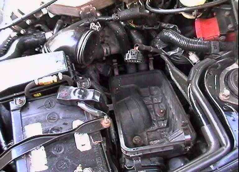
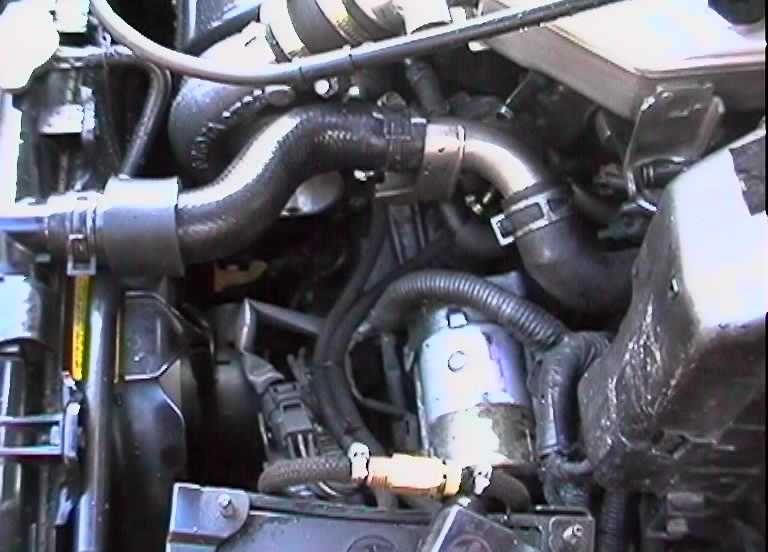
Determining the desired position

Take a few minutes to decide on the desired position of the relief valve. Questions to consider may be :-

Where can it be hidden out of site ?
Where can it be easily adjusted ?
Where can I route the piping ?

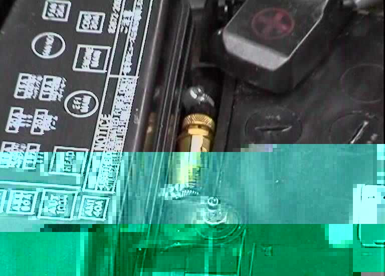
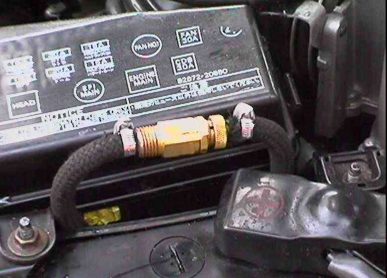
NOTE: The installation instructions below not only explain how to plumb in the relief valve but also highlight an ideal location for the valve between the fuse box and battery.

This picture shows an ideal location between the fuse box and battery … Relief valve installed on a GT4

Installation

The following instructions are based around a GT4 install however the principal is the same for any turbo-charged car. The important thing to remember is to ensure the flow of the air is from the turbo to the ball end of the relief valve to the waste-gate actuator. Where the relief valve is mounted is really incidental although pipe lengths should be kept to a minimum.

Remove AFM unit complete with the air filter. AFM unit removed
Undo 2 fuse box fixing nuts and rotate fuse box into the AFM area.
Remove AFM to turbo inlet hose. Removed AFM turbo hose
Locate and remove turbo to waste-gate actuator boost hose (short hose about 2 inches long). Routed boost hoses
Attach 1x50 cm hose to turbo outlet nipple and secure with 1 hose clip.
Attach 1x50 cm hose to the waste-gate actuator inlet nipple and secure with 1 hose clip. Attach hose to wastegate actuator
Adjust the relief valve so approximately half of the adjuster threads are showing – be careful not to completely undo the relief valve as the ball and spring may drop out.
Attach new turbo outlet hose to the relief valve.
Attach new waste-gate actuator inlet hose to the relief valve (knurled adjuster end).
Route hoses neatly down and along the wiring loom towards the battery (optional).
Locate relief valve on the battery (temporarily).
Refit AFM to turbo inlet hose – ensuring relief valve hoses are underneath the inlet hose.
Refit fuse box ensuring the relief valve hoses are sandwiched between the fuse box and battery and between the two fuse box mounting lugs. Location of relief valve
Refit AFM unit and air filter.

 
[ home | site map | back | forward | top ]